Physical Computing, Final Project
Physical Computing Final Project
Technical Details
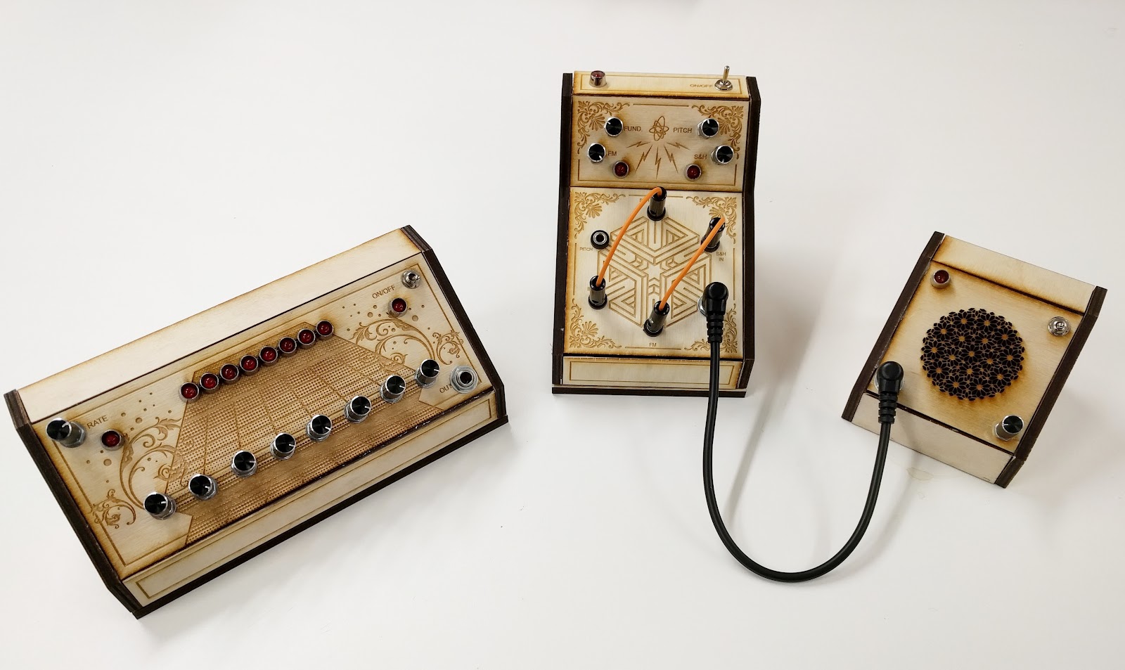
For my final project, I have made a set of analog synthesizers.
What I mean by analog is that I haven’t used any microcontrollers for this project. I will only be working with 9V batteries and a series of different IC’s ( Integrated circuits ).
These are the IC chips I have used for my final build:
- CD4046
- CD40106
- CD4066
- CD4017
- LM386
The Synthesizer
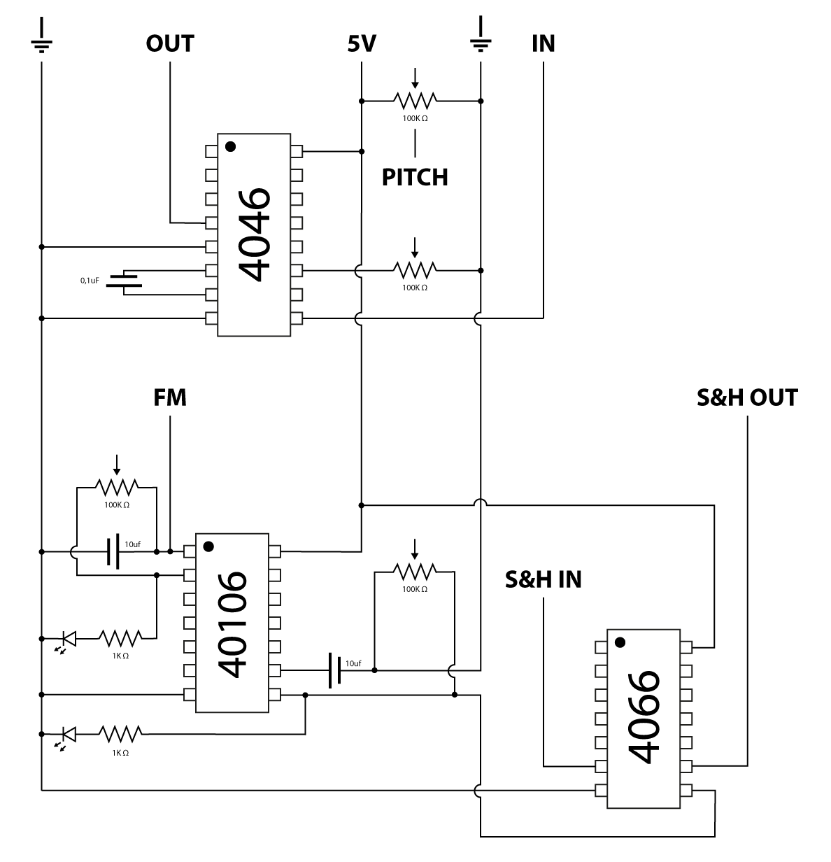
This is a very simple circuit that is generating a square wave. The small yellow 0.1uF capacitor is the capacitor that is setting the frequency range of the oscillator. The potentiometer is adjusting the fundamental frequency.
First oscillator prototype

This is how the oscillator sounds:
The next step is to add more effects to the synthesizer so it sounds a bit more interesting.
Next I am setting up another oscillator using the CD40106 chip. The CD40106 is a Hex Schmitt Trigger or more easier digestible, a logic chip.
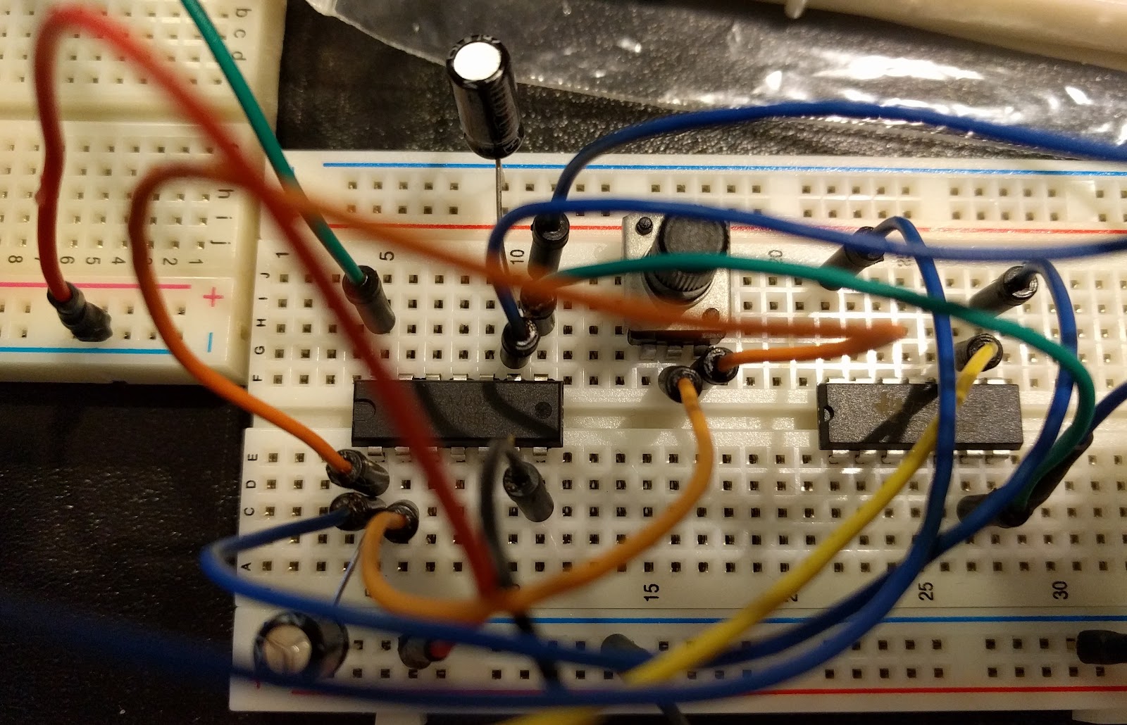
CD40106 ( left ) together with CD4066 ( right )
What determines the pitch of the oscillators is the relationship between the resistors and the capacitors. A very simplified explanation is that the capacitor will be filling up with charge and when it’s full, the capacitor will empty and the state of the trigger will change. This repeats as long as there is a power applied to the chip, this is what creates the oscillation. The bigger the capacitor, the longer it takes to fill up. This creates a much lower frequency, also known as LFO ( Low Frequency Oscillator ).
By adding the oscillators together we create an effect that is called Frequency Modulation.
The modulation rate is determined by the frequency of the second oscillator.
Frequency Modulation:
The final piece of the synthesizer is the CD4066 chip. This chip is helping to create an effect that is called Sample and Hold or S & H for short.
The CD4066 chip is used to sample the given input signal and to hold the sampled value. A very simplified explanation is that it’s basically taking a “snapshot” of the incoming signal and holding that sampled value as long as the capacitor is charged.
Schematic of the patchable synth.
Complete breadboard prototype of final build

This is how it sounds:
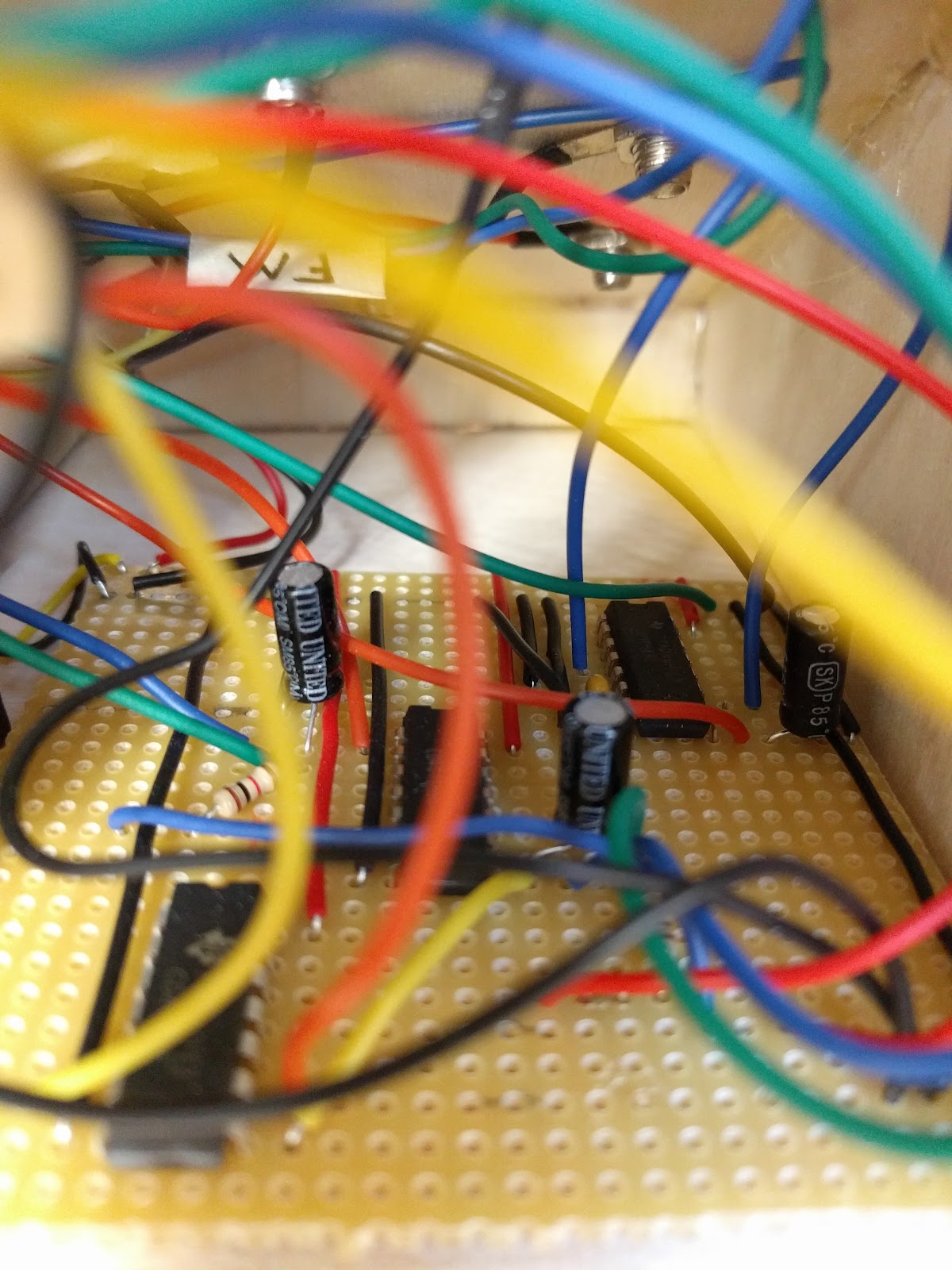
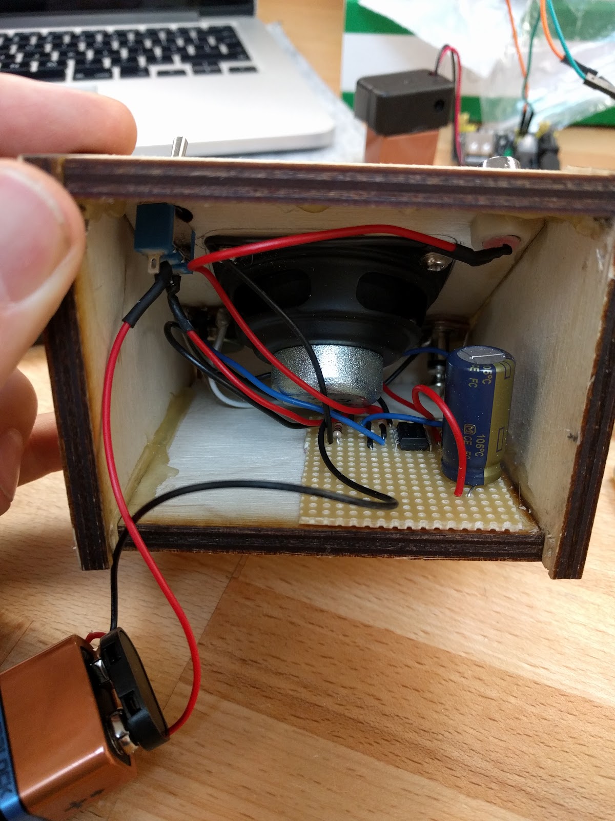
Protoboard mounted inside the enclosure

Protoboard close-up
Final outcome

Final build:
Play Session:
Play Session - Delay:
Play Session - Distortion:
Voltage Regulation
To achieve a stable voltage input of 5V, I created a voltage regulator using a toggle switch, two capacitor and a 7805 voltage regulator.
Voltage regulator schematics

The Sequencer
The step sequencer is basically nine oscillators generated by two CD40106 chips and two CD4017 chips. One LFO controls the speed of the sequencer and then one oscillator for each step, 8 steps in total.
One of the CD4017 chip is controlling the LEDs and one is controlling when to play the specific oscillator.
Whatever current passes through the potentiometer to charge the corresponding capacitor, it will get drained by the diode into the chip. This will result in that the oscillator won’t oscillate. When the CD4017’s output is HIGH, the diode works as a blockage and the oscillator will oscillate and you will hear that particular step.
Sequencer schematics
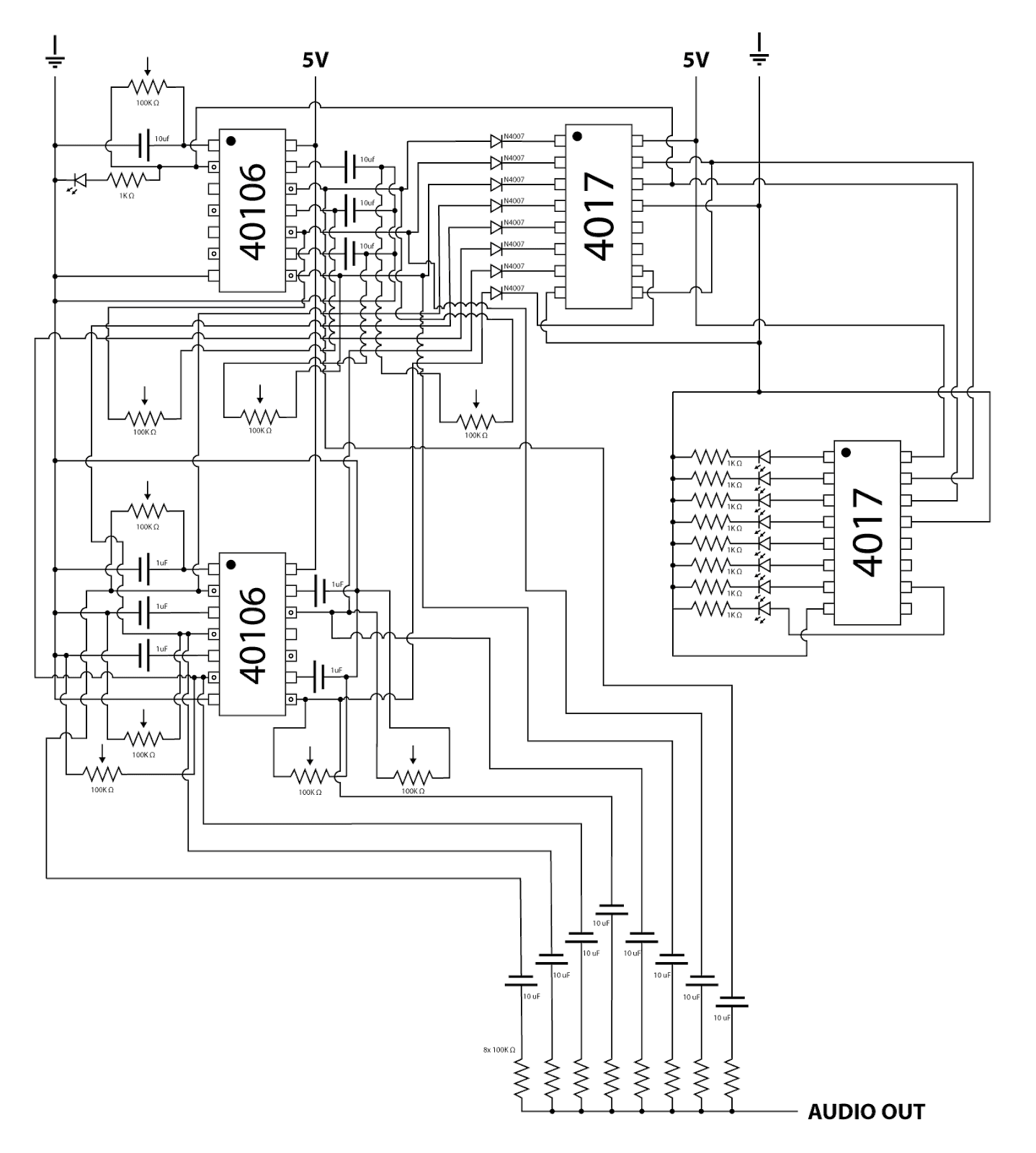
Image of a working sequencer on two breadboards

First prototype with 1 step:
Second prototype with 2 steps:
Final prototype:
Setting up the LEDs on the final protoboard

Protoboard close-up
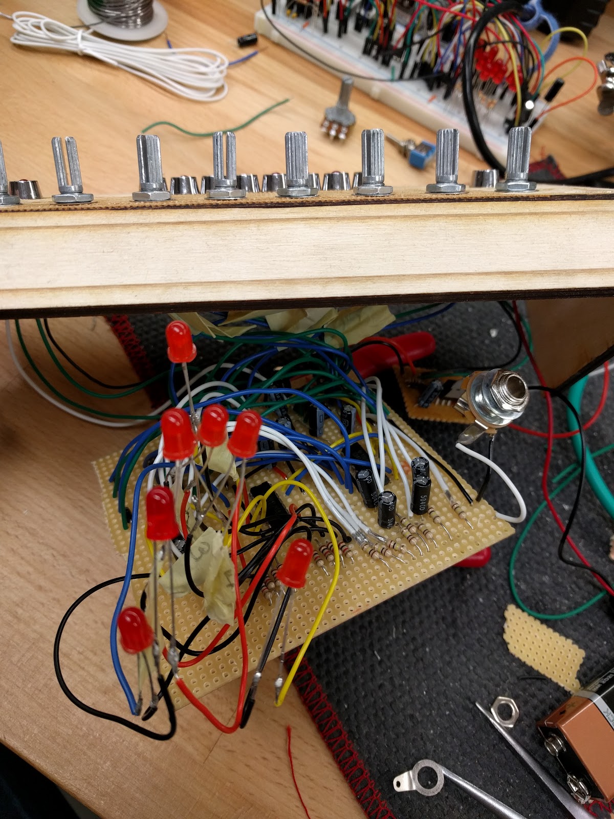
Mounting the potentiometers

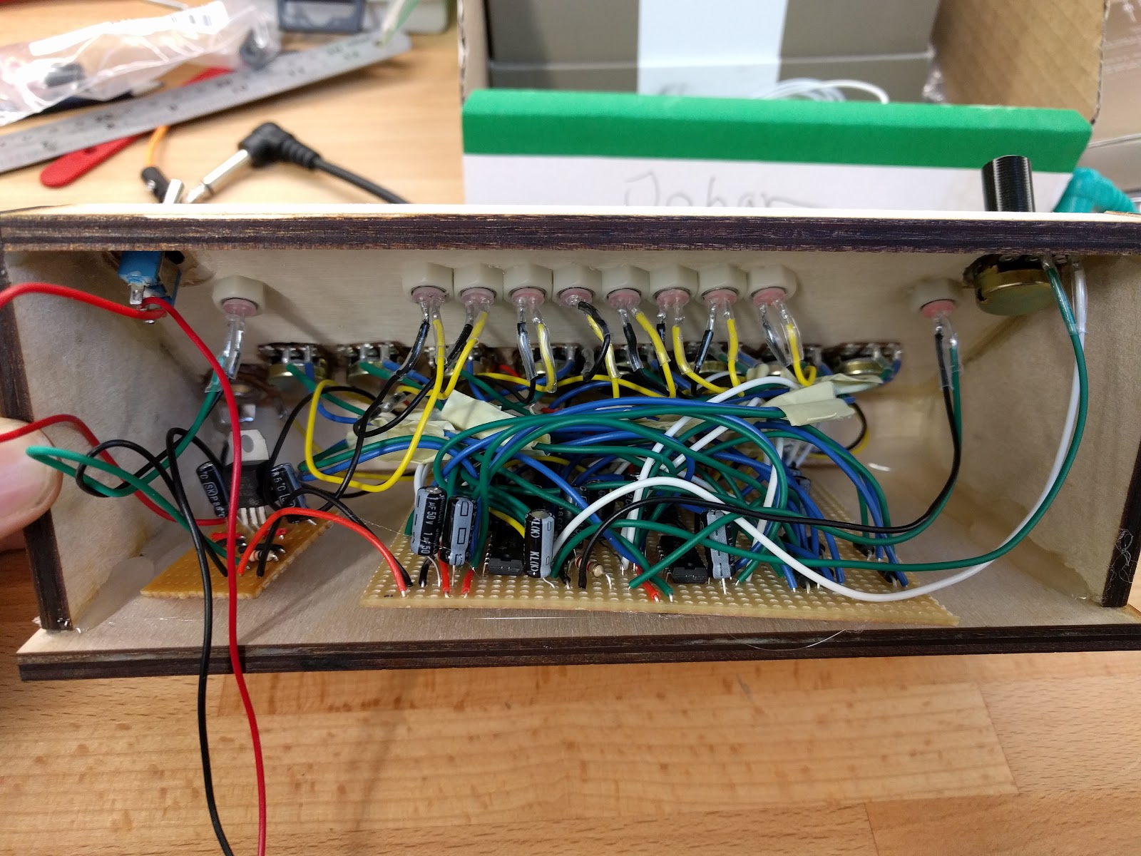
Back of the protoboard of the final build

Protoboard successfully mounted inside the enclosure
Final outcome

Final build:
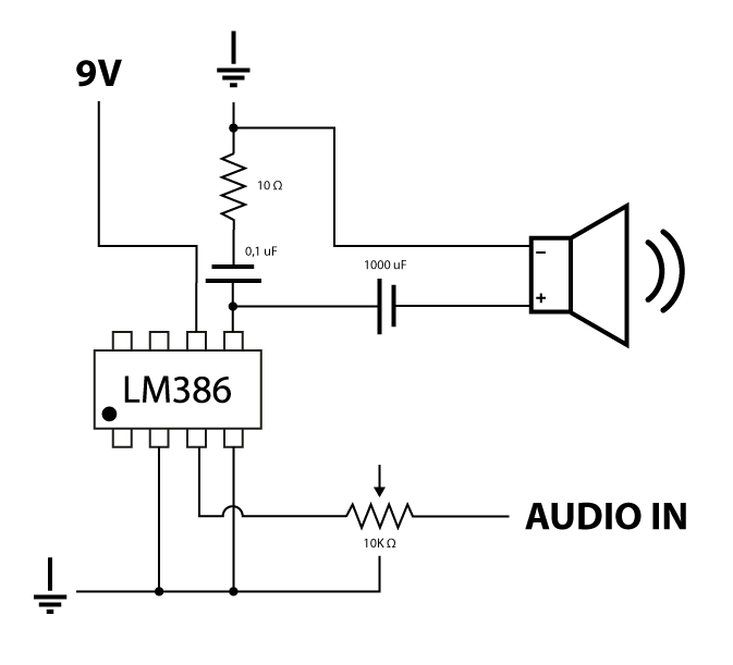
The Amplifier
The final piece of my project is the amplifier. It’s using a LM386 microchip, a 8Ω speaker, a 10KΩ potentiometer for volume control and a large capacitor of 1000uF.
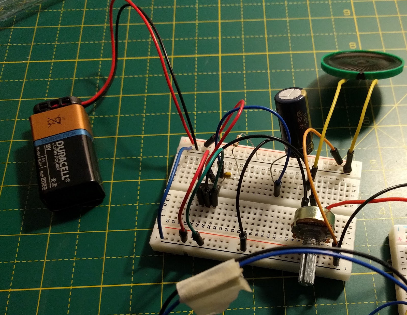
Amplifier prototype built on breadboard
Amplifier protoboard mounted inside speaker enclosure
Amplifier schematics
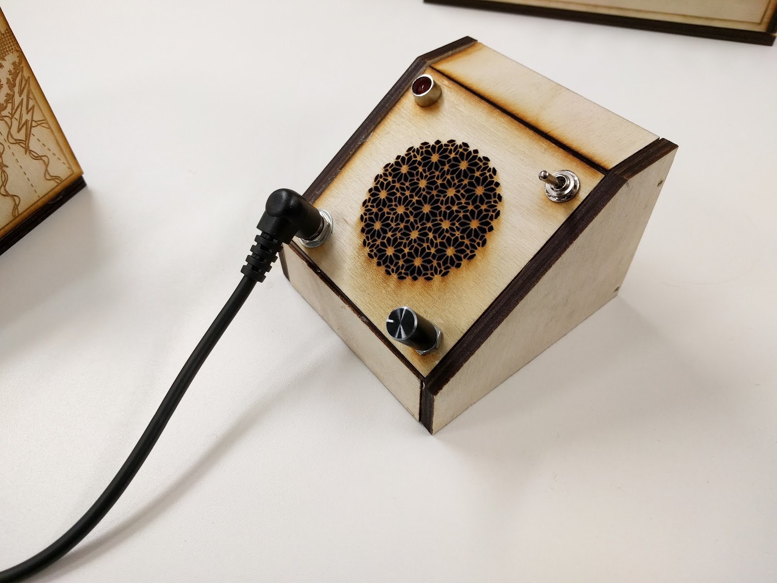
Final outcome
Design
I started the design process by making prototypes using cardboard and tape. Then when I got the measurements right, I used the laser cutter to create prototypes in cardboard before making the final engraved versions in wood.
To keep the aesthetics, I uses banana cables for my patch cables.They work as any other wire but they look nicer and have better feel and stability and they can also be daisy chained.
Patch cables


Cardboard prototypes


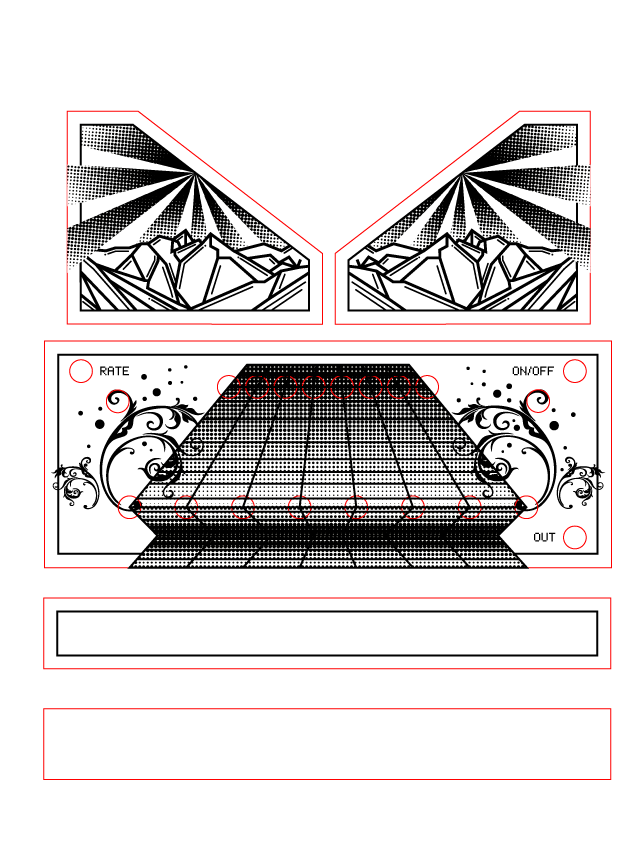
Synthesizer Module Design
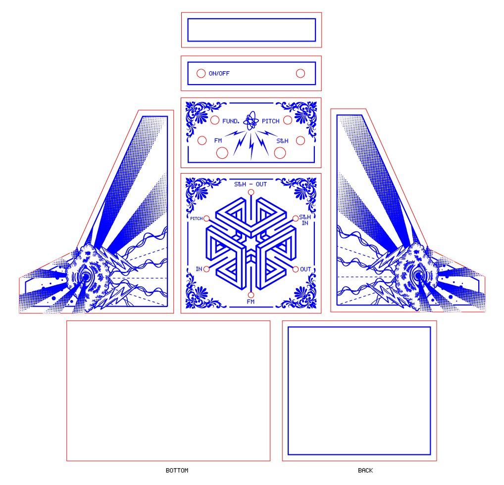
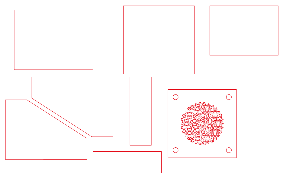
Sequencer Module Design
Speaker Module Design
Problems
I found out that you need to connect the audio source ground to the ground of the amplifier. If you don’t, you will get low amplitude and lots of noise. I didn’t want to ruin the aesthetics of the modules by adding an extra cable. I decided to change the output jack so it could hold both the audio signal and the ground. I used a 6.33mm mono jack instead. This also allows me to connect the synthesizer to other devices, such as guitar pedals and other amplifiers. It ended up being a much better solution in the end.
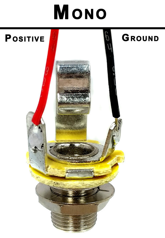
Source: Google
Another problem I had was that the output signal for each oscillator in my sequencer seemed to carry lots of noise and they also varied in amplitude.
My solution was to create a kind of “audio mixer”. I added a 100KΩ resistor at the end of each output signal so that all carried the same type of signal to the final audio output.
I also made some errors when I measured my potentiometers. I calculated the diameter of the knob but forgot to calculate the bottom of the potentiometer which is much wider. This ended up with the potentiometers not fitting next to each other and I had to retake my measurements a few times.
Resources:
Logic noise tutorials by Elliot Williams:
Other resources:
Comments
Post a Comment